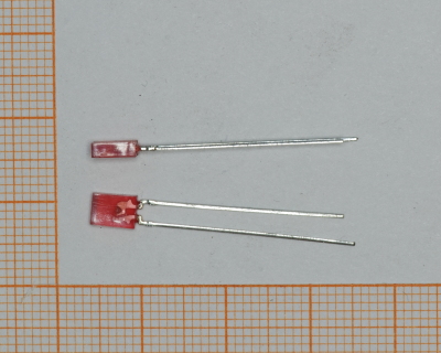
 Red
Flat LED
493
Red
Flat LED
493
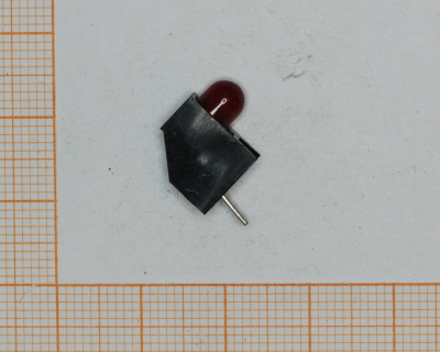 Red
5mm
747
Red
5mm
747
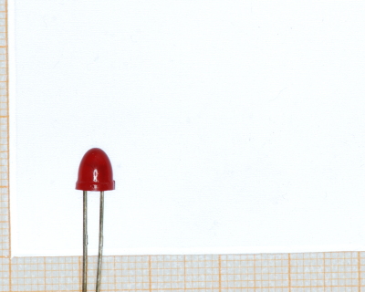 Red LED
1377
Red LED
Red LED
1377
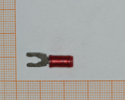 Red terminal connectors
546
Red terminal connectors
546
 Red test point
 used to permit inspection and testing of circuits
134
Alligator clip ends with red rubber covers
Alligator clip ends with red rubber covers
1589
Red test point
Red test point used to permit inspection and testing of circuits
134
Alligator clip ends with red rubber covers
Alligator clip ends with red rubber covers
1589
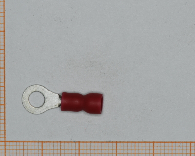 Connector Lug, Red
182
Connector Lug, Red
182
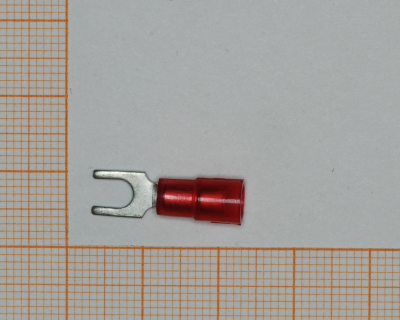 Fork spade connector, red #6 (22-18)
235
Fork spade connector, red #6 (22-18)
235
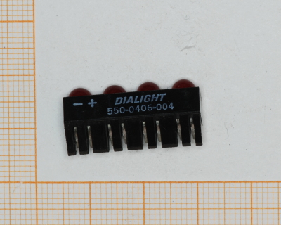 550-0406-004
Red
729
550-0406-004
Red
729
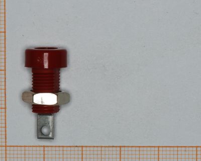 Banana socket
red
230
Banana socket
red
230
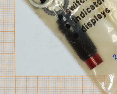 DIALIGHT PANEL MOUNT INDICATOR
LED, 9.53MM, RED, 5V
Mounting Hole Size: 0.375” (9.53 mm)
Max Panel Thickness: 0.312” (7.92 mm)
Operating Voltage: 3.6, 5, 10, 14 and 28V DC
Color: Red
515
DIALIGHT PANEL MOUNT INDICATOR
LED, 9.53MM, RED, 5V
Mounting Hole Size: 0.375” (9.53 mm)
Max Panel Thickness: 0.312” (7.92 mm)
Operating Voltage: 3.6, 5, 10, 14 and 28V DC
Color: Red
515
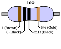 10
5% tolerance
1057
10
5% tolerance
1057
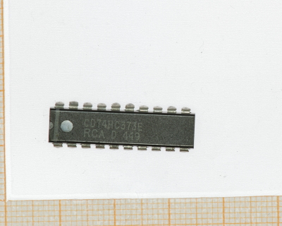 CD74HC373E
2-V to 6-V VCC Operation
Wide Operating Temperature Range of
–55°C to 125°C
Balanced Propagation Delays and
Transition Times
Standard Outputs Drive up to 15 LS-TTL
Loads
Significant Power Reduction Compared to
LS-TTL Logic ICs
1438
CD74HC373E
2-V to 6-V VCC Operation
Wide Operating Temperature Range of
–55°C to 125°C
Balanced Propagation Delays and
Transition Times
Standard Outputs Drive up to 15 LS-TTL
Loads
Significant Power Reduction Compared to
LS-TTL Logic ICs
1438
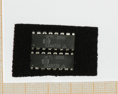 HCTL-2000
• Interfaces Encoder to
Microprocessor
• 14 MHz Clock Operation
• Full 4X Decode
• High Noise Immunity:
Schmitt Trigger Inputs Digital
Noise Filter
• 12 or 16-Bit Binary Up/
Down Counter
• Latched Outputs
• 8-Bit Tristate Interface
• 8, 12, or 16-Bit Operating
Modes
• Quadrature Decoder Output
Signals, Up/Down and Count
• Cascade Output Signals, Up/
Down and Count
• Substantially Reduced
System Software
1424
npn infrared phototransistor
new in radio shack packaging!
3050
HCTL-2000
• Interfaces Encoder to
Microprocessor
• 14 MHz Clock Operation
• Full 4X Decode
• High Noise Immunity:
Schmitt Trigger Inputs Digital
Noise Filter
• 12 or 16-Bit Binary Up/
Down Counter
• Latched Outputs
• 8-Bit Tristate Interface
• 8, 12, or 16-Bit Operating
Modes
• Quadrature Decoder Output
Signals, Up/Down and Count
• Cascade Output Signals, Up/
Down and Count
• Substantially Reduced
System Software
1424
npn infrared phototransistor
new in radio shack packaging!
3050
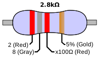 2.8k
0.25
29
2.8k
0.25
29
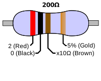 200
0.25W
14
200
0.25W
14
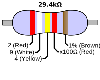 29.4k
0.25
37
29.4k
0.25
37
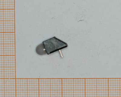 Bi-Color LED Circuit Board Indicator
550-3006
727
Bi-Color LED Circuit Board Indicator
550-3006
727
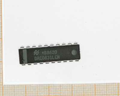 DAC0831LCN
8-bit Accuracy DAC
Easily Interfaces to Most Microcontrollers
Double-Buffered, Single Buffered or Flow Through Options
Linearity Specified with Zero and Full Scale Adjust
Operates Stand-Alone
1428
DAC0831LCN
8-bit Accuracy DAC
Easily Interfaces to Most Microcontrollers
Double-Buffered, Single Buffered or Flow Through Options
Linearity Specified with Zero and Full Scale Adjust
Operates Stand-Alone
1428
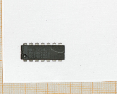 DM74LS74A
This device contains two independent
positive-edge-triggered D flip-flops with complementary outputs. The information on the D input is accepted by the flip-flops on the positive going edge of the clock pulse. The
triggering occurs at a voltage level and is not directly related to the transition time of the rising edge of the clock. The data on the D input may be changed while the clock is low or high
without affecting the outputs as long as the data setup and hold times are not violated. A low logic level on the preset or clear inputs will set or reset the outputs regardless of the logic levels of the other inputs.
1425
DM74LS74A
This device contains two independent
positive-edge-triggered D flip-flops with complementary outputs. The information on the D input is accepted by the flip-flops on the positive going edge of the clock pulse. The
triggering occurs at a voltage level and is not directly related to the transition time of the rising edge of the clock. The data on the D input may be changed while the clock is low or high
without affecting the outputs as long as the data setup and hold times are not violated. A low logic level on the preset or clear inputs will set or reset the outputs regardless of the logic levels of the other inputs.
1425
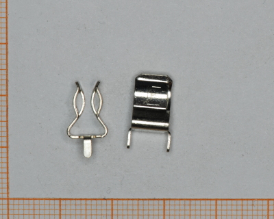 Fuse Holder
Separately soldered.
137
Fuse Holder
Separately soldered.
137
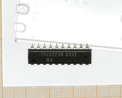 SN74LS373N
Choice of Eight Latches or Eight D-Type
Flip-Flops in a Single Package
3-State Bus-Driving Outputs
Full Parallel Access for Loading
Buffered Control Inputs
Clock-Enable Input Has Hysteresis to
Improve Noise Rejection (’S373 and ’S374)
P-N-P Inputs Reduce DC Loading on Data
Lines (’S373 and ’S374)
1439
toroids (assorted)
magnetic wired donuts!
1401
SN74LS373N
Choice of Eight Latches or Eight D-Type
Flip-Flops in a Single Package
3-State Bus-Driving Outputs
Full Parallel Access for Loading
Buffered Control Inputs
Clock-Enable Input Has Hysteresis to
Improve Noise Rejection (’S373 and ’S374)
P-N-P Inputs Reduce DC Loading on Data
Lines (’S373 and ’S374)
1439
toroids (assorted)
magnetic wired donuts!
1401
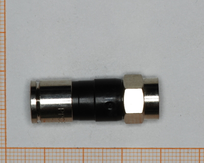 2x8 idc connector
16 pin, 2x8, 0.1" pin spacing. Crimp on ribbon cables. eurorack power connectors.
255
2x8 idc connector
16 pin, 2x8, 0.1" pin spacing. Crimp on ribbon cables. eurorack power connectors.
255
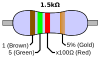 1.5k
P=0.25W
49
1.5k
P=0.25W
49
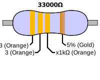 33000
0.25w
32
33000
0.25w
32
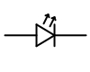 TIL31B
P-N GALLIUM ARSENIDE INFRARED-EMITTING DIODES
732
TIL31B
P-N GALLIUM ARSENIDE INFRARED-EMITTING DIODES
732